Choosing the right Cnc Motion Controller can shape a machine’s accuracy, speed, and everyday reliability. A controller that looks powerful on paper may still struggle with a specific motor, drive, or cutting process. That matters.
Picture a router tracing a tight curve while its spindle cuts through hardwood. If motion commands arrive unevenly, the edge may show marks, even when the machine frame is rigid. The controller must coordinate the required axes, process motion smoothly, and communicate reliably with the drives and other equipment. Small details count: supported feedback devices, pulse rates, input and output options, and compatible software can affect setup and operation.
The best choice depends on the machine, not just a feature list. Consider the number of axes, the motors and drives already installed, the required accuracy, and the control functions operators use. A mill running short production cycles may need different capabilities from a large router handling long toolpaths. There is no single specification that guarantees good results. That is easy to overlook.
This guide explains how to compare controller types, check compatibility, and weigh performance against cost and support. It also points out questions worth asking manufacturers before purchase, including how updates are handled and what troubleshooting help is available. Specifications are a useful starting point, but a practical test with your own machine can reveal problems a brochure misses. Even then, some trade-offs remain. A careful selection process helps reduce surprises and gives the machine a more dependable foundation.
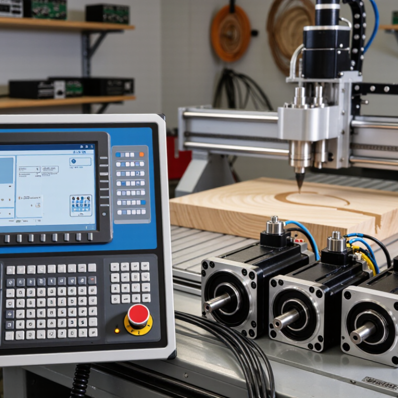
A CNC motion controller translates a programmed tool path into coordinated machine movement. It reads commands, such as G-code, and calculates where each axis should move and when. It sends timed signals to motor drives, which supply power to the motors. The controller usually does not power the motors directly. That distinction matters.
When a program calls for a diagonal move, the controller coordinates multiple axes. This keeps the tool moving along the intended path. It manages acceleration and deceleration to reduce abrupt starts and stops. Depending on the system, it may also handle homing, limit switches, spindle commands, and emergency-stop inputs. Some controllers use feedback from encoders; others rely on commanded steps without confirming the actual position.
When choosing a controller, check that it supports your machine’s axes, motor drives, input signals, and required motion features. A small router may need fewer inputs than a machine with a tool changer or rotary axis. Confirm how it handles travel limits and interrupted moves, too. These details can be easy to miss. A controller cannot fix a loose coupling, worn bearing, or incorrect tool offset. The setup is rarely perfect, so allow time to test movements at low speed and adjust settings carefully.
Start with the machine, not the controller’s feature list. A router cutting plywood needs different motion behavior from a five-axis mill finishing steel. List axis count, travel, spindle speed, target feed rate, encoder type, and interpolation needs. Then confirm the controller can coordinate the axes at the required cycle time. A fast processor is not enough if the drives, feedback devices, or I/O cannot keep pace. Measure real cutting loads; catalog values alone can mislead. That matters. Leave room for future tooling, but avoid paying for unused channels.
Factory context changes the choice, too. The International Federation of Robotics’ World Robotics 2024 reports 541,302 industrial robot installations in 2023 and 4,281,585 robots operating worldwide at year’s end. Those figures do not mean every CNC cell needs robot integration. They do highlight the value of planning interfaces: check fieldbus support, synchronized I/O, safety connections, and recovery after communication faults. A stand-alone machine may need less connectivity. Not always.
Test the controller with a heavy workpiece and a representative toolpath. Watch contour error, vibration, and recovery behavior, not just stated positioning resolution. If jobs change often, test recipe changes and operator access. A controller can meet its specification and still feel awkward on the shop floor. That gap deserves a second look.
Controller types differ in how they process motion commands and handle feedback. Standalone controllers suit focused machines with stable, repeatable jobs. PC-based systems offer flexibility for complex toolpaths and frequent software changes. PLC-based motion control can fit production cells that coordinate CNC axes with sensors and other equipment. The best choice depends on the whole machine, not a headline speed.
Compare practical performance: axis count, interpolation rate, command-update interval, feedback resolution, and communication latency. A fast update rate is useful only if the drive, encoder, and mechanics can keep pace. Check how the controller behaves during abrupt direction changes; a visible pause at a corner can affect finish quality.
The International Federation of Robotics’ World Robotics 2024 report counted 4,281,585 industrial robots operating worldwide in 2023. That figure reflects growing automation, but it does not prove one controller type is universally better. Trade-offs remain.
Tips: Test a representative toolpath, not just a brochure specification. Record cycle time, contour error, and surface finish, then repeat under realistic load. Small differences matter. A controller that performs well on paper may still need tuning, and that uncertainty deserves attention.
A controller must match the machine’s electrical and mechanical limits. Check motor type, encoder feedback, pulse or fieldbus interface, and available input/output points. Then compare voltage, current, and connector details against the machine drawings. A familiar connector is not proof of compatibility. Test the planned setup with the actual drive and a spare motor, if possible.
Software matters just as much. Confirm that the controller supports your preferred programming workflow, toolpath formats, and required functions, such as homing and probing. Check whether configuration tools run on your shop computers and whether licenses restrict maintenance or backups. Keep a copy of the machine parameters. Small detail, big impact. I would still verify firmware behavior under load; a clean simulation can miss real timing issues.
Support should be specific, not just friendly. Ask for wiring diagrams, version histories, troubleshooting steps, and realistic response times. The World Economic Forum’s 2023 Future of Jobs Report estimates that 44% of workers’ skills will be disrupted by 2027, while 60% will need training. That makes clear documentation and practical training important when controls change. Ask who handles difficult cases, and whether help is available after installation. A vague promise can leave a technician waiting beside a stopped machine.
How to Choose the Best CNC Motion Controller?
How to Compare Options and Verify Your Choice
Compare controllers against the machine’s real workload, not a feature checklist. Count the axes, record peak and continuous speeds, and note whether coordinated moves, spindle synchronization, or encoder feedback are essential. Then ask suppliers for cycle-time data, contouring error, and communication update rates under comparable conditions. Numbers matter. A fast update rate alone does not guarantee accurate motion; mechanics, tuning, and feedback also affect results.
Deloitte’s 2024 Smart Manufacturing Survey found that 86% of surveyed manufacturing executives expect smart manufacturing to drive competitiveness within five years. That broad industry signal supports careful evaluation of connected controls, but it is not proof that a particular controller will improve a specific CNC machine. Check compatibility with the drive, motor, encoder, programming environment, and safety architecture. Request the test conditions behind performance claims. Vague benchmarks are a warning.
Verify shortlisted options on a representative machine or test rig. Run the same toolpath, material, feed rate, and load, then compare cycle time, position error, surface finish, and recovery after a fault. Keep the results. A small pilot may expose tuning work or integration costs that a brochure misses. I would also revisit assumptions after testing; early comparisons can overlook operator workflow and maintenance needs. That is not always convenient. Cite the report as Deloitte, 2024 Smart Manufacturing Survey, and treat its findings as context, not a substitute for machine-level evidence.
It converts a programmed toolpath into coordinated axis movements. It reads commands and sends timed signals to motor drives. It usually does not power the motors directly. That distinction matters.
It synchronizes multiple axes so the tool follows the intended path. It also manages acceleration and deceleration. Abrupt starts can affect movement.
No. Some use encoder feedback to check position. Others track commanded steps without confirming where the machine actually moved. Worth checking.
Standalone systems can suit stable, repeatable jobs. PC-based systems offer flexibility for complex toolpaths and software changes. PLC-based control can coordinate axes with sensors and other equipment.
Check axis count, interpolation rate, update interval, feedback resolution, and communication latency. A fast update rate helps only when the drives and mechanics can keep pace. Test corners, too.
Compare motor type, encoder feedback, interfaces, input and output points, voltage, and current against machine drawings. A familiar connector proves little.
Confirm support for your programming workflow, toolpath formats, homing, and probing. Check configuration tools, license limits, backups, wiring diagrams, and response times. Keep parameter copies.
Run a representative toolpath at low speed, then record cycle time, contour error, and surface finish under realistic load. Repeat the test. A clean simulation can still miss timing problems.
Not by itself. Loose couplings, worn bearings, or incorrect tool offsets can still cause trouble. I would inspect those before blaming the controller.
Choosing the right Cnc Motion Controller starts with understanding its role: it interprets control commands and coordinates a machine’s motors and movements. Begin by defining your machine’s requirements, including the number of axes, motor types, required precision, operating speed, and the complexity of the tasks it will perform. These needs help determine which controller type and performance level are suitable, without paying for capabilities your machine does not require.
Next, check that the controller works with your machine’s motors, drives, sensors, and other components. Review its software, communication interfaces, setup process, documentation, and available technical support. Compare potential options against your requirements, paying attention to reliability, expandability, ease of use, and overall cost. Before making a final choice, verify compatibility using specifications and, where possible, test the controller with the intended system. This practical approach can help you select a solution that supports accurate, dependable operation and future needs.